
Dither

Dither is an intentionally applied form of noise used to randomize quantization error, preventing large-scale patterns such as color banding in images. Dither is routinely used in processing of both digital audio and video data, and is often one of the last stages of mastering audio to a CD.
A common use of dither is converting a grayscale image to black and white, such that the density of black dots in the new image approximates the average gray level in the original.
Etymology[edit]
The term dither was published in books on analog computation and hydraulically controlled guns shortly after World War II.[1][2][nb 1] Though he did not use the term dither, the concept of dithering to reduce quantization patterns was first applied by Lawrence G. Roberts[4] in his 1961 MIT master's thesis[5] and 1962 article.[6] By 1964 dither was being used in the modern sense described in this article.[7] The technique was in use at least as early as 1915, though not under the name dither.[8]
In digital processing and waveform analysis[edit]
Dither is utilized in many different fields where digital processing and analysis are used. These uses include systems using digital signal processing, such as digital audio, digital video, digital photography, seismology, radar and weather forecasting systems.
Quantization yields error. If that error is correlated to the signal, the result is potentially cyclical or predictable. In some fields, especially where the receptor is sensitive to such artifacts, cyclical errors yield undesirable artifacts. In these fields introducing dither converts the error to random noise. The field of audio is a primary example of this. The human ear functions much like a Fourier transform, wherein it hears individual frequencies.[9][10] The ear is therefore very sensitive to distortion, or additional frequency content, but far less sensitive to additional random noise at all frequencies such as found in a dithered signal.[11][failed verification]
Digital audio[edit]
In an analog system, the signal is continuous, but in a PCM digital system, the amplitude of the signal out of the digital system is limited to one of a set of fixed values or numbers. This process is called quantization. Each coded value is a discrete step... if a signal is quantized without using dither, there will be quantization distortion related to the original input signal... In order to prevent this, the signal is "dithered", a process that mathematically removes the harmonics or other highly undesirable distortions entirely, and that replaces it with a constant, fixed noise level.[12]
The final version of audio that goes onto a compact disc contains only 16 bits per sample, but throughout the production process, a greater number of bits are typically used to represent the sample, this must be reduced to 16 bits to make the CD.
There are multiple ways to do this. One can, for example, simply discard the excess bits – called truncation. One can also round the excess bits to the nearest value. Each of these methods, however, results in predictable and determinable errors in the result. Using dither replaces these errors with a constant, fixed noise level.
Examples[edit]


Take, for example, a waveform that consists of the following values:
1 2 3 4 5 6 7 8
If the waveform is reduced by 20%, then the following are the new values:
0.8 1.6 2.4 3.2 4.0 4.8 5.6 6.4
If these values are truncated it results in the following data:
0 1 2 3 4 4 5 6
If these values are rounded instead it results in the following data:
1 2 2 3 4 5 6 6
For any original waveform, the process of reducing the waveform amplitude by 20% results in regular errors. Take for example a sine wave that, for some portion, matches the values above. Every time the sine wave's value hit 3.2, the truncated result would be off by 0.2, as in the sample data above. Every time the sine wave's value hit 4.0, there would be no error since the truncated result would be off by 0.0, also shown above. The magnitude of this error changes regularly and repeatedly throughout the sine wave's cycle. It is precisely this error that manifests itself as distortion. What the ear hears as distortion is the additional content at discrete frequencies created by the regular and repeated quantization error.
A plausible solution would be to take the 2 digit number (say, 4.8) and round it one direction or the other. For example, it could be rounded to 5 one time and then 4 the next time. This would make the long-term average 4.5 instead of 4, so that over the long-term the value is closer to its actual value. This, on the other hand, still results in determinable (though more complicated) error. Every other time the value 4.8 comes up the result is an error of 0.2, and the other times it is −0.8. This still results in a repeating, quantifiable error.
Another plausible solution would be to take 4.8 and round it so that the first four times out of five it is rounded up to 5, and the fifth time it is rounded to 4. This would average out to exactly 4.8 over the long term. Unfortunately, however, it still results in repeatable and determinable errors, and those errors still manifest themselves as distortion to the ear.
This leads to the dither solution. Rather than predictably rounding up or down in a repeating pattern, it is possible to round up or down in a random pattern. If a series of random numbers between 0.0 and 0.9 (ex: 0.6, 0.1, 0.3, 0.6, 0.9, etc.) is generated and added to the 4.8, two times out of ten the result will truncate back to 4 (if 0.0 or 0.1 are added to 4.8) and eight times out of ten it will truncate to 5. Each given situation has a random 20% chance of rounding to 4 or 80% chance of rounding to 5. Over the long haul, these results will average to 4.8 and their quantization error will be random noise. This noise is less offensive to the ear than the determinable distortion that other solutions would produce.
Usage[edit]
Dither is added before any quantization or re-quantization process, in order to de-correlate the quantization noise from the input signal and to prevent non-linear behavior (distortion). Quantization with lesser bit depth requires higher amounts of dither. The result of the process still yields distortion, but the distortion is of a random nature so the resulting noise is, effectively, de-correlated from the intended signal.
In a seminal paper published in the AES Journal, Lipshitz and Vanderkooy pointed out that different noise types, with different probability density functions (PDFs) behave differently when used as dither signals,[13] and suggested optimal levels of dither signal for audio. Gaussian noise requires a higher level of added noise for full elimination of audible distortion than noise with rectangular or triangular distribution. Triangular distributed noise also minimizes noise modulation – audible changes in the volume level of residual noise behind quiet music that draw attention to the noise.[14]
Dither can be useful to break up periodic limit cycles, which are a common problem in digital filters. Random noise is typically less objectionable than the harmonic tones produced by limit cycles.
Noise distributions[edit]
Rectangular probability density function (RPDF) dither noise has a uniform distribution; any value in the specified range has the same probability of occurring.
Triangular probability density function (TPDF) dither noise has a triangular distribution; values in the center of the range have a higher probability of occurring. Triangular distribution can be achieved by adding two independent RPDF sources.
Gaussian PDF has a normal distribution. The relationship of probabilities of results follows a bell-shaped, or Gaussian curve, typical of dither generated by analog sources such as microphone preamplifiers. If the bit depth of a recording is sufficiently great, that preamplifier noise will be sufficient to dither the recording.
Noise shaping is a filtering process that shapes the spectral energy of quantization error, typically to either de-emphasize frequencies to which the ear is most sensitive or separate the signal and noise bands completely. If dither is used, its final spectrum depends on whether it is added inside or outside the feedback loop of the noise shaper. If inside, the dither is treated as part of the error signal and shaped along with actual quantization error. If outside, the dither is treated as part of the original signal and linearises quantization without being shaped itself. In this case, the final noise floor is the sum of the flat dither spectrum and the shaped quantization noise. While real-world noise shaping usually includes in-loop dithering, it is also possible to use it without adding dither at all, in which case quantization error is evident at low signal levels.
Colored dither is sometimes mentioned as dither that has been filtered to be different from white noise. Noise shaping is one such application.
Which noise distribution to use[edit]
If the signal being dithered is to undergo further processing, then it should be processed with a triangular-type dither that has an amplitude of two quantization steps so that the dither values computed range from, for example, −1 to +1, or 0 to 2.[13] This is the lowest power ideal dither, in that it does not introduce noise modulation (which would manifest as a constant noise floor), and eliminates the harmonic distortion from quantization. If a colored dither is used instead at these intermediate processing stages, then frequency content may bleed into other frequency ranges that are more noticeable and become distractingly audible.
If the signal being dithered is to undergo no further processing – if it is being dithered to its final result for distribution – then a colored dither or noise shaping is appropriate. This can effectively lower the audible noise level, by putting most of that noise in a frequency range where it is less critical.
Digital photography and image processing[edit]


Dithering is used in computer graphics to create the illusion of color depth in images on systems with a limited color palette. In a dithered image, colors that are not available in the palette are approximated by a diffusion of colored pixels from within the available palette.[15] The human eye perceives the diffusion as a mixture of the colors within it (see color vision). Dithered images, particularly those using palettes with relatively few colors, can often be distinguished by a characteristic graininess or speckled appearance.
Dithering introduces noise or a pattern into an image, and often the patterning is visible. In these circumstances, it has been shown that dither generated from blue noise is the least unsightly and distracting.[16] The error diffusion techniques were some of the first methods to generate blue-noise dithering patterns. However, other techniques such as ordered dithering can also generate blue-noise dithering without the tendency to degenerate into areas with artifacts.
Examples[edit]

Reducing the color depth of an image can have significant visual side effects. If the original image is a photograph, it is likely to have thousands or even millions of distinct colors. The process of constraining the available colors to a specific color palette effectively throws away a certain amount of color information.
A number of factors can affect the resulting quality of a color-reduced image. Perhaps most significant is the color palette that will be used in the reduced image. For example, an original image (Figure 1) may be reduced to the 216-color web-safe palette. If the original pixel colors are simply translated into the closest available color from the palette, no dithering will occur (Figure 2). However, typically this approach will result in flat areas (contours) and a loss of detail and may produce patches of color that are significantly different from the original. Shaded or gradient areas may produce color banding which may be distracting. The application of dithering can help to minimize such visual artifacts and usually results in a better representation of the original (Figure 3). Dithering helps to reduce color banding and flatness.
One of the problems associated with using a fixed color palette is that many of the needed colors may not be available in the palette, and many of the available colors may not be needed; a fixed palette containing mostly shades of green would not be well-suited for an image of a desert, for instance. The use of an optimized color palette can be of benefit in such cases. An optimized color palette is one in which the available colors are chosen based on how frequently they are used in the original source image. If the image is reduced based on an optimized palette the result is often much closer to the original (Figure 4).
The number of colors available in the palette is also a contributing factor. If, for example, the palette is limited to only 16 colors then the resulting image could suffer from additional loss of detail, resulting in even more pronounced problems with flatness and color banding (Figure 5). Once again, dithering can help to minimize such artifacts (Figure 6).
-
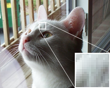 Figure 1. Original photo; note the smoothness in the detail.
 -
 Figure 2. Original image using the web-safe color palette with no dithering applied. Note the large flat areas and loss of detail.
 -
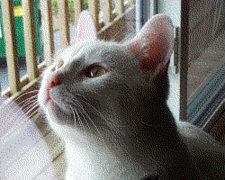 Figure 3. Original image using the web-safe color palette with Floyd–Steinberg dithering. Note that even though the same palette is used, the application of dithering gives a better representation of the original.
 -
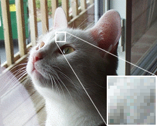 Figure 4. Here, the original has been reduced to a 256-color optimized palette with Floyd–Steinberg dithering applied. The use of an optimized palette, rather than a fixed palette, allows the result to better represent the colors in the original image.
 -
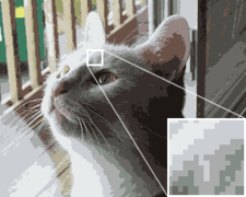 Figure 5. Depth is reduced to a 16-color optimized palette in this image, with no dithering. Colors appear muted, and color banding is pronounced.
 -
 Figure 6. This image also uses the 16-color optimized palette, but the use of dithering helps to reduce banding.


Applications[edit]

One common application of dithering is to more accurately display graphics containing a greater range of colors than the display hardware is capable of showing. For example, dithering might be used in order to display a photographic image containing millions of colors on video hardware that is only capable of showing 256 colors at a time. The 256 available colors would be used to generate a dithered approximation of the original image. Without dithering, the colors in the original image would be quantized to the closest available color, resulting in a displayed image that is a poor representation of the original.
The very earliest uses were to reduce images to 1-bit black and white. This may have been done for printing even earlier than for bit-mapped video graphics. It was common for making images to display on 1-bit video displays for X and Apollo and similar Unix workstations. The dithering was usually pre-computed and only the dithered image was stored; computation and memory were far too limited to compute it live.
An example home computer users may have seen was emulation of lower resolution CGA 4 color graphics on higher resolution monochrome Hercules graphics cards, with the colors being translated to ordered dither patterns.[17][18][19]
Some liquid-crystal displays use temporal dithering to achieve a similar effect. By alternating each pixel's color value rapidly between two approximate colors in the panel's color space, a display panel that natively supports only 18-bit color (6 bits per channel) can represent a 24-bit color image (8 bits per channel).[20]
Dithering such as this, in which the computer's display hardware is the primary limitation on color depth, is commonly employed in software such as web browsers. Since a web browser may be retrieving graphical elements from an external source, it may be necessary for the browser to perform dithering on images with too many colors for the available display. It was due to problems with dithering that a color palette known as the web-safe color palette was identified, for use in choosing colors that would not be dithered on systems capable of displaying only 256 colors simultaneously.
But even when the total number of available colors in the display hardware is high enough to properly render full-color digital photographs, banding may still be evident to the eye, especially in large areas of smooth shade transitions. Modest dithering can resolve this without making the image appear grainy. High-end still image processing software commonly uses these techniques for improved display.
Another useful application of dithering is for situations in which the graphics file format is the limiting factor. In particular, the commonly used GIF format is restricted to the use of 256 or fewer colors.[a] Images such as these have a defined color palette containing a limited number of colors that the image may use. For such situations, graphical editing software may be responsible for dithering images prior to saving them in such restrictive formats.
Dithering is analogous to the halftone technique used in printing. For this reason, the term dithering is sometimes used interchangeably with the term halftoning, particularly in association with digital printing.
The ability of inkjet printers to print isolated dots has increased the use of dithering in printing. A typical desktop inkjet printer can print, at most, just 16 colors as this is the combination of dot or no dot from cyan, magenta, yellow and black print heads.[b] To reproduce a large range of colors, dithering is used. In densely printed areas, where the color is dark the dithering is not always visible because the dots of ink merge producing a more uniform print. However, a close inspection of the light areas of a print where dots are further apart reveals dithering patterns.
Algorithms[edit]
There are several algorithms designed to perform dithering. One of the earliest, and still one of the most popular, is the Floyd–Steinberg dithering algorithm, which was developed in 1975. One of the strengths of this algorithm is that it minimizes visual artifacts through an error-diffusion process; error-diffusion algorithms typically produce images that more closely represent the original than simpler dithering algorithms.[21]
Dithering methods include:
- Thresholding (also average dithering[22]): each pixel value is compared against a fixed threshold. This may be the simplest dithering algorithm there is, but it results in immense loss of detail and contouring.[21]
- Random dithering was the first attempt (at least as early as 1951[23]) to remedy the drawbacks of thresholding. Each pixel value is compared against a random threshold, resulting in a staticky image. Although this method does not generate patterned artifacts, the noise tends to swamp the detail of the image. It is analogous to the practice of mezzotinting.[21]
- Patterning dithers using a fixed pattern. For each of the input values, a fixed pattern is placed in the output image. The biggest disadvantage of this technique is that the output image is larger (by a factor of the fixed pattern size) than the input pattern.[21]
- Ordered dithering dithers using a dither matrix. For every pixel in the image, the value of the pattern at the corresponding location is used as a threshold. Neighboring pixels do not affect each other, making this form of dithering suitable for use in animations. Different patterns can generate completely different dithering effects. Though simple to implement, this dithering algorithm is not easily changed to work with free-form, arbitrary palettes.
- A halftone dithering matrix produces a look similar to that of halftone screening in newspapers. This is a form of clustered dithering, in that dots tend to cluster together. This can help hide the adverse effects of blurry pixels found on some older output devices. The primary use for this method is in offset printing and laser printers. In both these devices, the ink or toner prefers to clump together and will not form the isolated dots generated by the other dithering methods.
- A Bayer matrix[21] produces a very distinctive cross-hatch pattern.
- A matrix tuned for blue noise, such as those generated by the void-and-cluster method,[24] produces a look closer to that of an error diffusion dither method.
| (Original) | Threshold | Random |
|---|---|---|

|

|

|
| Halftone | Ordered (Bayer) | Ordered (void-and-cluster) |

|

|

|
- Error-diffusion dithering is a feedback process that diffuses the quantization error to neighboring pixels.
- Floyd–Steinberg (FS) dithering only diffuses the error to neighboring pixels. This results in very fine-grained dithering.
- Minimized average error dithering by Jarvis, Judice, and Ninke diffuses the error also to pixels one step further away. The dithering is coarser but has fewer visual artifacts. However, it is slower than Floyd–Steinberg dithering, because it distributes errors among 12 nearby pixels instead of 4 nearby pixels for Floyd–Steinberg.
- Stucki dithering is based on the above, but is slightly faster. Its output tends to be clean and sharp.
- Burkes dithering is a simplified form of Stucki dithering that is faster, but is less clean than Stucki dithering.
| Floyd–Steinberg | Jarvis, Judice & Ninke | Stucki | Burkes |
|---|---|---|---|

|

|

|

|
- Error-diffusion dithering (continued):
- Sierra dithering is based on Jarvis dithering, but it is faster while giving similar results.
- Two-row Sierra is the above method but was modified by Sierra to improve its speed.
- Filter Lite is an algorithm by Sierra that is much simpler and faster than Floyd–Steinberg, while still yielding similar results.
- Atkinson dithering was developed by Apple programmer Bill Atkinson, and resembles Jarvis dithering and Sierra dithering, but it is faster. Another difference is that it does not diffuse the entire quantization error, but only three quarters. It tends to preserve detail well, but very light and dark areas may appear blown out.
- Gradient-based error-diffusion dithering was developed in 2016[25] to remove the structural artifact produced in the original FS algorithm by a modulated randomization, and to enhance the structures by a gradient-based diffusion modulation.
| Sierra | Two-row Sierra | Sierra Lite | Atkinson | Gradient-based |
|---|---|---|---|---|

|

|

|

|

|
- Dithering methods based on physical models:
- Lattice-Boltzmann Dithering is based on Lattice Boltzmann methods and was developed to provide a rotationally invariant alternative to Error-diffusion dithering [26]
- Electrostatic Halftoning is modeled after the principles of Electrostatics, which has a low approximation error and creates few visual artifacts[27]
| Lattice-Boltzmann |
|---|

|
Other applications[edit]
This section needs expansion with: See Talk:Dither#Noise. You can help by adding to it. (December 2022) |
Stimulated Brillouin scattering (SBS) is a nonlinear optical effect that limits the launched optical power in fiber optic systems. This power limit can be increased by dithering the transmit optical center frequency, typically implemented by modulating the laser's bias input. See also polarization scrambling.
Phase dithering can be used to improve the quality of the output in direct digital synthesis.[28] Another common application is to get through EMC tests by using spread spectrum clock dithering of frequency to smear out single frequency peaks.[29]
Another type of temporal dithering has recently been introduced in financial markets, in order to reduce the incentive to engage in high-frequency trading. ParFX, a London foreign exchange market that began trading in 2013, imposes brief random delays on all incoming orders; other currency exchanges are reportedly experimenting with the technique. The use of such temporal buffering or dithering has been advocated more broadly in financial trading of equities, commodities, and derivatives.[30]
See also[edit]
- Anti-aliasing (disambiguation)
- Color quantization
- Jitter
- Stick-slip phenomenon
- Stippling
- Stochastic resonance
- Spot wobble
Notes[edit]
- ^ …[O]ne of the earliest [applications] of dither came in World War II. Airplane bombers used mechanical computers to perform navigation and bomb trajectory calculations. Curiously, these computers (boxes filled with hundreds of gears and cogs) performed more accurately when flying on board the aircraft, and less well on ground. Engineers realized that the vibration from the aircraft reduced the error from sticky moving parts. Instead of moving in short jerks, they moved more continuously. Small vibrating motors were built into the computers, and their vibration was called dither from the Middle English verb "didderen," meaning "to tremble." Today, when you tap a mechanical meter to increase its accuracy, you are applying dither, and modern dictionaries define dither as a highly nervous, confused, or agitated state. In minute quantities, dither successfully makes a digitization system a little more analog in the good sense of the word. Ken Pohlmann, Principles of Digital Audio[3]
References[edit]
- ^ William C. Farmer (1945). Ordnance Field Guide: Restricted. Military service publishing company.
- ^ Korn, Granino Arthur; Korn, Theresa M. (1952). Electronic Analog Computers: (d–c Analog Computers). McGraw-Hill.
- ^ Ken C. Pohlmann (2005). Principles of Digital Audio. McGraw-Hill Professional. ISBN 978-0-07-144156-8.
- ^ Thomas J. Lynch (1985). Data Compression: Techniques and Applications. Lifetime Learning Publications. ISBN 978-0-534-03418-4.
- ^ Lawrence G. Roberts, Picture Coding Using Pseudo-Random Noise, MIT, S.M. thesis, 1961 online Archived 26 September 2006 at the Wayback Machine
- ^ Lawrence G. Roberts (February 1962). "Picture Coding Using Pseudo-Random Noise". IEEE Transactions on Information Theory. 8 (2): 145–154. doi:10.1109/TIT.1962.1057702.
- ^ L. Schuchman (December 1964). "Dither Signals and Their Effect on Quantization Noise". IEEE Trans. Commun. 12 (4): 162–165. doi:10.1109/TCOM.1964.1088973.
- ^ Comment by L. P. Ferris at the end of A. E. Kennelly; F. A. Laws; P. H. Pierce (1915). "Experimental researches on skin effect in conductors". Transactions of the American Institute of Electrical Engineers. 35 (2): 1953–2021. doi:10.1109/T-AIEE.1915.4765283. S2CID 51654558.
- ^ Deutsch, Diana (1999). The psychology of music. Gulf Professional Publishing. p. 153. ISBN 978-0-12-213565-1.
- ^ Hauser, Marc D. (1998). The evolution of communication. MIT Press. p. 190. ISBN 978-0-262-58155-4.
- ^ Montgomery, Christopher (Monty) (2012–2013). "Digital Show and Tell". Xiph.Org / Red Hat, Inc. Retrieved 27 February 2013.
Dither is specially-constructed noise that substitutes for the noise produced by simple quantization. Dither doesn't drown out or mask quantization noise, it replaces it with noise characteristics of our choosing that aren't influenced by the input.
- ^ Mastering Audio: The Art and the Science by Bob Katz, pages 49–50, ISBN 978-0-240-80545-0
- ^ a b Vanderkooy, John; Lipshitz, Stanley P (December 1987). "Dither in Digital Audio". J. Audio Eng. Soc. 35 (12): 966–975. Retrieved 28 October 2009.
- ^ Lipshitz, Stanley P; Vanderkooy, John; Wannamaker, Robert A. (November 1991). "Minimally Audible Noise Shaping". J. Audio Eng. Soc. 39 (11): 836–852. Retrieved 28 October 2009.
- ^ "Dithering for Pixel Artists". 18 January 2021.
- ^ Ulichney, Robert A (1994). "Halftone Characterization in the Frequency Domain" (PDF). Archived from the original (PDF) on 14 February 2014. Retrieved 12 August 2013.
- ^ "ibm pc - How do CGA emulators for Hercules graphics work?". Retrocomputing Stack Exchange. Retrieved 7 February 2021.
- ^ "DOS Days - CGA Simulators for Hercules Cards". www.dosdays.co.uk. Retrieved 3 December 2022.
- ^ "The Programmer's Corner » SIMCGA41.ZIP » Display Utilities". www.pcorner.com. Retrieved 3 December 2022.
- ^ "6-Bit vs. 8-Bit... PVA/MVA vs. TN+Film – Are Things Changing?". TFT Central. Archived from the original on 10 April 2008. Retrieved 6 February 2008.
- ^ a b c d e Crocker, Lee Daniel; Boulay, Paul; Morra, Mike (20 June 1991). "Digital Halftoning". Computer Lab and Reference Library. Archived from the original on 27 September 2007. Retrieved 10 September 2007. Note: this article contains a minor mistake: "(To fully reproduce our 256-level image, we would need to use an 8x8 pattern.)" The bold part should read "16x16".
- ^ Silva, Aristófanes Correia; Lucena, Paula Salgado; Figuerola, Wilfredo Blanco (13 December 2000). "Average Dithering". Image Based Artistic Dithering. Visgraf Lab. Retrieved 10 September 2007.
- ^ Goodall, W. M. (1951). "Television by pulse code modulation". Bell Syst. Tech. J. 30: 33–49. doi:10.1002/j.1538-7305.1951.tb01365.x.
- ^ Ulichney, Robert A (1993). "The void-and-cluster method for dither array generation" (PDF). Retrieved 11 February 2014.
- ^ Xiangyu Y. Hu (2016). "Simple gradient-based error-diffusion method" (abstract). Journal of Electronic Imaging. 25 (4): 043029. Bibcode:2016JEI....25d3029H. doi:10.1117/1.JEI.25.4.043029. S2CID 35527501.
- ^ Hagenburg, Kai; Breuß, Michael; Vogel, Oliver; Weickert, Joachim; Welk, Martin (2009). "A Lattice Boltzmann Model for Rotationally Invariant Dithering". Advances in Visual Computing (PDF). Lecture Notes in Computer Science. Vol. 5876. Springer Berlin Heidelberg. pp. 949–959. doi:10.1007/978-3-642-10520-3_91. eISSN 1611-3349. ISBN 978-3-642-10519-7. ISSN 0302-9743.
- ^ Schmaltz, Christian; Gwosdek, Pascal; Bruhn, Andrés; Weickert, Joachim (10 November 2010). "Electrostatic Halftoning". Computer Graphics Forum. 29 (8): 2313–2327. doi:10.1111/j.1467-8659.2010.01716.x. ISSN 0167-7055. S2CID 10776881.
- ^ "11", A Technical Tutorial on Digital Signal Synthesis (PDF), Analog Devices, 1999
- ^ Lauder, D.; Moritz, M. (2000). Investigation into possible effects resulting from dithered clock oscillators on EMC measurements and interference to radio transmission systems. University of Hertfordshire. Archived from the original on 13 July 2012. Retrieved 25 May 2013.
- ^ Mannix, Brian F. (January 2013). "Races, Rushes, and Runs: Taming the Turbulence in Financial Trading" (PDF) (working paper). Archived from the original (PDF) on 3 September 2021. Retrieved 9 July 2018.
External links[edit]
- "Dither – Not All Noise Is Bad"
- What is Dither? Article previously published in Australian HI-FI with visual examples of how audio dither sharply reduces high order harmonic distortion.
- Aldrich, Nika. "Dither Explained"
- DHALF Explains a lot about dithering, and also includes sufficient detail to implement several dithering algorithms.
- Dither Vibration Example
- Stan Lipshitz Research in the field of dither for audio was done by Lipshitz, Vanderkooy, and Wannamaker at the University of Waterloo